最近在写比赛的文档的时候,写到了BH1750的参数之类的,于是想着想都想了,不如写下来玩玩。
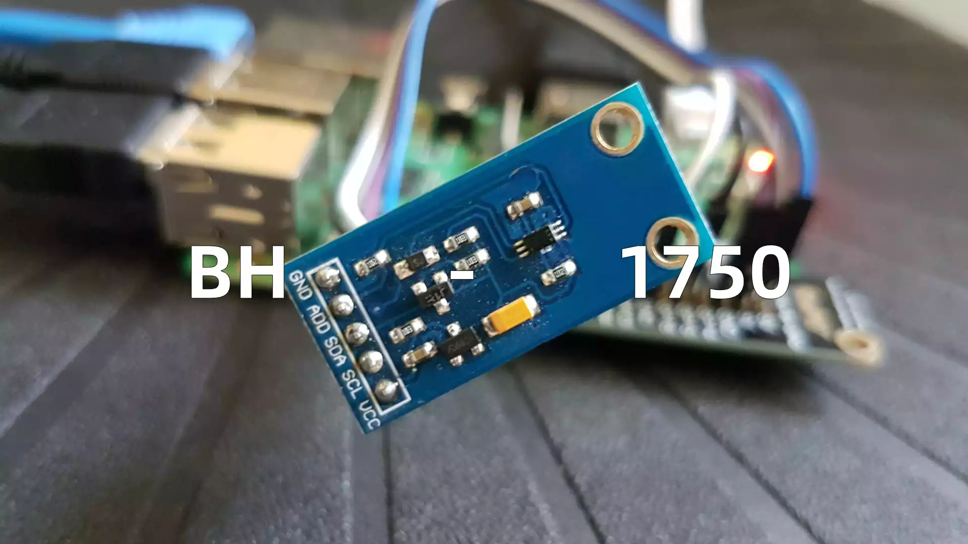
模块和芯片 而BH1750是一款数字型的光强传感器片上集成芯片,采用标准I2C总线协议与MCU进行链接。
GY-30模块的实质是BH1750,只是把外围诸如滤波和电容之类的电路整合进去了而已,其实都是用的BH1750芯片。
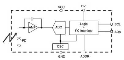
BH1750内部电路是由:光敏二极管、运算放大器、AD转换器等组成。光敏二极管通过光伏效应接收光信号产生电信号,经过运算放大后,由AD转换器采集电压数据并转换为数字信号,然后储存在寄存器之中。BH1750支持完全的I2C协议,使用I2C总线发送特定的控制位,即可读取光强度数据,亦可以修改BH1750的采集模式。
引脚定义 BH1750支持且仅支持完整的I2C总线,采用四线传输方式,但由于BH1750模块本身可以从硬件对其设备地址进行修改,所以还多一个修改位。
名称
说明
VCC
接入 3.3V 电源正极
SCL
I2C时钟同步总线
SDA
I2C实际数据总线
ADDR
I2C设备地址切换线;低电平:0x23,高电平:0x5C
GND
接地或者电源负极
I2C协议 前面说到,BH1750模块支持完整的I2C总线协议。I2C总线是由飞利浦公司推出的串行、半双工总线,它是总线通讯,可以在总线上最高挂载112个设备(含保留地址则为127个设备)。
I2C总线是一种多主机总线,连接在 I2C总线上的器件分为主机和从机。 主机有权发起和结束一次通信,从机只能被动呼叫。每个I2C设备有一个唯一的7bit地址,由于需要告知从机是读取还是写入,所以在实际使用中会增加一个bit作为控制,实际使用中是8个bit地址。BH1750的通讯过程
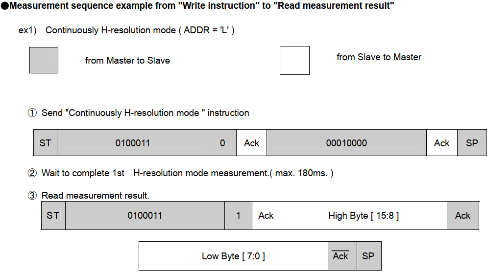
首先我们看数据手册,可以发现BH1750的数据收发分为两个8bit合共16个bit的数据(不算ACK)。数据结构于英文文档之下表如下:
在实际使用中,Slave Address与R/W数据可以一起传输,即7bit+1bit = 8bit
传输路径跟其他I2C设备一样,发送Slave Address → 等ACK应答 → 发送Opecode数据 → 等ACK应答。
第一步:发送上电指令 (0x01)
假设ADDR为低电平,BH1750设备地址为0x23 + R0 = 0x46。数据结构为:0x46 WaitACK 0x01 WaitACK
第二步:发送测量模式指令 (0x10)
根据图片上和第一步的例子,我们假定ADDR低电平且采用连续H分辨率测量的模式(0x10)
数据结构为:0x46 WaitACK 0x10 WaitAC
第三步:等测量和读数据
手册上对每个测量模式的时间有说,连续H分辨率需要的时间最长,平均为120ms,但是为了数据最新,最好是隔200ms读取一次。值得一提的是,寄存器数据不会清零,因此亦可以不延迟直接读取,只是有点误差。
现在,是读取模式,与之前的0x23 + R0 = 0x46的地址不同,读取模式是0x23 + W1 = 0x47的地址。
因此数据结构为:0x47 WaitACK 读出的数据 WaitACK
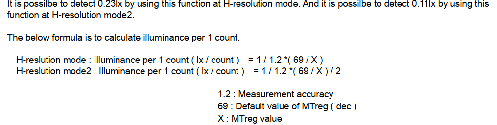
第四步:计算实际光照值
前面读出来的值,显然的是BH1750内部传感器的值,并不是真实的光照强度值,根据手册,我们需要转换一下。
H模式: 光照强度 = 1 / 1.2 * (寄存器值[15:0] * 分辨率)单位是lx
H2模式:光照强度 = 1 / 1.2 * (寄存器值[15:0] * 分辨率) / 2单位是lx
BH1750的指令和测量模式 所有指令
名称
地址
注释
断电 Power Down
0000_0000
无激活状态 No active state.
上电 Power On
0000_0001
通电等待测量指令 Waiting for measurement command.
重置 Reset
0000_0111
重置寄存器的所有值 Reset Data register value. Reset command is not acceptable in Power Down mode.
连续H分辨率模式 Continuously H-Resolution Mode
0001_0000
在1lx分辨率下开始连续测量 Start measurement at 1lx resolution. Measurement Time is typically 120ms.
连续H分辨率模式2 Continuously H-Resolution Mode2
0001_0001
在0.5lx分辨率下开始连续测量 Start measurement at 0.5lx resolution. Measurement Time is typically 120ms.
连续L分辨率模式 Continuously L-Resolution Mode
0001_0011
在4lx分辨率下开始连续测量 Start measurement at 4lx resolution. Measurement Time is typically 16ms.
一次H分辨率模式 One Time H-Resolution Mode
0010_0000
在1lx分辨率下开始测量一次,完成后进入断电模式 Start measurement at 1lx resolution. Measurement Time is typically 120ms. It is automatically set to Power Down mode after measurement.
一次H分辨率模式2 One Time H-Resolution Mode2
0010_0001
在0.5lx分辨率下开始测量一次,完成后进入断电模式 Start measurement at 0.5lx resolution. Measurement Time is typically 120ms. It is automatically set to Power Down mode after measurement.
一次L分辨率模式 One Time L-Resolution Mode
0010_0011
在4lx分辨率下开始测量一次,完成后进入断电模式 Start measurement at 4lx resolution. Measurement Time is typically 16ms. It is automatically set to Power Down mode after measurement.
Change Measurement time ( High bit )
01000_MT[7,6,5]
Change measurement time. ※ Please refer “adjust measurement result for influence of optical window.”
Change Masurement time ( Low bit )
011_MT[4,3,2,1,0]
Change measurement time. ※ Please refer “adjust measurement result for influence of optical window.”
各类测量模式
测量模式
精度
测量时间
注释
一次H分辨率模式
1 lx
120ms
进行一次测量,测量完成后会切换到断电模式
一次H分辨率模式2
0.5 lx
120ms
进行一次测量,测量完成后会切换到断电模式
一次L分辨率模式
4 lx
16ms
进行一次测量,测量完成后会切换到断电模式
连续H分辨率模式
1 lx
120ms
会自动进行连续测量,无需重复配置
连续H分辨率模式2
0.5 lx
120ms
会自动进行连续测量,无需重复配置
连续L分辨率模式
4 lx
16ms
会自动进行连续测量,无需重复配置
编程和代码部分 下面的编程我以stm32为例,I2C和BH1750都是标准协议,其实换成其他单片机或者系统,程序也是基本一样的,不同的只是GPIO口的不同。
这边用的就还是软件模拟I2C的方式,没有用硬件I2C。
1. 头文件定义部分 1 2 3 4 5 6 7 8 9 10 11 12 13 14 15 16 17 18 19 20 21 22 23 24 25 26 27 28 29 30 31 32 33 34 35 36 37 38 39 40 #ifndef __BH1750_H__ #define __BH1750_H__ #include "stm32f10x.h" #include "Delay.h" /** * author: 御枫林下 on Tue, 28 May 2024 * brief: 宏定义GOIO引脚 * param: void * return: void **/ #define BH1750_I2C_GPIO_Port GPIOB #define BH1750_I2C_SCL_GPIOPin GPIO_Pin_6 #define BH1750_I2C_SDA_GPIOPin GPIO_Pin_7 #define BH1750_I2C_SCL(x) GPIO_WriteBit(BH1750_I2C_GPIO_Port, BH1750_I2C_SCL_GPIOPin, (x)) #define BH1750_I2C_SDA(x) GPIO_WriteBit(BH1750_I2C_GPIO_Port, BH1750_I2C_SDA_GPIOPin, (x)) #define BH1750_I2C_SDARead() GPIO_ReadInputDataBit(BH1750_I2C_GPIO_Port, BH1750_I2C_SDA_GPIOPin) #define HIGH Bit_SET #define LOW Bit_RESET /** * author: 御枫林下 on Tue, 28 May 2024 * brief: 宏定义BH1750相关地址 **/ #define BH1750_ADDRESS 0x46 #define BH1750_CMD_AddWrite 0x46 #define BH1750_CMD_AddRead 0x47 #define BH1750_CMD_PowOn 0x01 #define BH1750_CMD_ModeH1 0x10 /** * author: 御枫林下 on Wed, 21 May 2024 * brief: 过滤需要用到的函数 * note: 不在此列的函数,无法在外部调用。为了保证函数在本体的可用性,在源文件内会重新定义一次。 **/ void BH1750_Init(void); uint16_t BH1750_FluxValue(void); uint16_t BH1750_ReadData(void); #endif
2. BH1750部分 1 2 3 4 5 6 7 8 9 10 11 12 13 14 15 16 17 18 19 20 21 22 23 24 25 26 27 28 29 30 31 32 33 34 35 36 37 38 39 40 41 42 43 44 45 46 47 48 49 50 51 52 53 54 55 56 57 58 59 60 61 62 63 64 65 66 67 68 69 70 71 72 73 74 75 76 77 78 79 80 81 82 83 84 85 86 87 88 89 90 91 92 93 94 95 96 97 98 99 100 101 102 103 104 105 106 107 108 109 110 111 112 113 114 115 116 117 118 119 120 121 122 123 124 125 126 127 128 129 130 131 132 133 134 135 136 137 138 139 140 141 142 143 144 145 146 147 148 149 150 151 152 153 154 155 156 157 158 159 160 161 162 163 164 165 166 167 168 169 170 171 172 173 174 175 176 177 178 179 180 181 #include "BH1750.h" /** * author: 御枫林下 on Wed, 21 May 2024 * brief: 定义所有函数 **/ static void BH1750_I2C_GPIOInit(void); void BH1750_I2C_Start(void); void BH1750_I2C_Stop(void); void BH1750_I2C_SendByte(uint8_t Byte); uint8_t BH1750_I2C_ReadByte(void); uint8_t BH1750_I2C_WaitAck(void); uint16_t BH1750_FluxValue(void); void BH1750_Init(void); /** * author: 御枫林下 on Wed, 21 May 2024 * brief: GPIO初始化函数 * param: void * return: void **/ static void BH1750_I2C_GPIOInit(void) { RCC_APB2PeriphClockCmd(RCC_APB2Periph_GPIOB, ENABLE); GPIO_InitTypeDef GPIO_InitStructure; GPIO_InitStructure.GPIO_Pin = BH1750_I2C_SCL_GPIOPin | BH1750_I2C_SDA_GPIOPin; GPIO_InitStructure.GPIO_Mode = GPIO_Mode_Out_OD; GPIO_InitStructure.GPIO_Speed = GPIO_Speed_50MHz; GPIO_Init(BH1750_I2C_GPIO_Port, &GPIO_InitStructure); BH1750_I2C_SDA(HIGH); BH1750_I2C_SCL(HIGH); } void BH1750_I2C_Start(void) { BH1750_I2C_SDA(HIGH); BH1750_I2C_SCL(HIGH); Delay_us(10); BH1750_I2C_SDA(LOW); Delay_us(10); BH1750_I2C_SCL(LOW); Delay_us(10); } void BH1750_I2C_Stop(void) { BH1750_I2C_SCL(LOW); BH1750_I2C_SDA(LOW); Delay_us(10); BH1750_I2C_SCL(HIGH); Delay_us(10); BH1750_I2C_SDA(HIGH); Delay_us(10); } void BH1750_I2C_SendByte(uint8_t Byte) { for (uint8_t i = 0; i < 8; i++) { BH1750_I2C_SDA(Byte & (0x80 >> i) ? HIGH : LOW); BH1750_I2C_SCL(HIGH); Delay_us(10); BH1750_I2C_SCL(LOW); Delay_us(10); } } uint8_t BH1750_I2C_ReadByte(void) { uint8_t byte = 0x00; BH1750_I2C_SDA(HIGH); Delay_us(10); for (uint8_t i = 0; i < 8; i++) { BH1750_I2C_SCL(HIGH); Delay_us(10); if (BH1750_I2C_SDARead()) { byte |= (0x80 >> i); } BH1750_I2C_SCL(LOW); Delay_us(10); } return byte; } uint8_t BH1750_I2C_WaitAck(void) { uint8_t AckTag = 0; BH1750_I2C_SDA(HIGH); BH1750_I2C_SCL(HIGH); Delay_us(10); if (BH1750_I2C_SDARead()) { AckTag = 1; } BH1750_I2C_SCL(LOW); Delay_us(10); return AckTag; } void BH1750_I2C_SendAck(void) { BH1750_I2C_SDA(LOW); Delay_us(10); BH1750_I2C_SCL(HIGH); Delay_us(10); BH1750_I2C_SCL(LOW); Delay_us(10); } void BH1750_I2C_SendNAck(void) { BH1750_I2C_SDA(HIGH); Delay_us(10); BH1750_I2C_SCL(HIGH); Delay_us(10); BH1750_I2C_SCL(LOW); Delay_us(10); } uint8_t BH1750_SendData(uint8_t data) { BH1750_I2C_Start(); BH1750_I2C_SendByte(BH1750_CMD_AddWrite); if (BH1750_I2C_WaitAck()) { BH1750_I2C_Stop(); return 1; } BH1750_I2C_SendByte(data); if (BH1750_I2C_WaitAck()) { BH1750_I2C_Stop(); return 2; } BH1750_I2C_Stop(); return 0; } uint16_t BH1750_ReadData(void) { uint8_t MSB, LSB; BH1750_I2C_Start(); BH1750_I2C_SendByte(BH1750_CMD_AddRead); if (BH1750_I2C_WaitAck()) { BH1750_I2C_Stop(); return 0; } MSB = BH1750_I2C_ReadByte(); BH1750_I2C_SendAck(); LSB = BH1750_I2C_ReadByte(); BH1750_I2C_SendNAck(); BH1750_I2C_Stop(); return (MSB << 8) | LSB; } /** * author: 御枫林下 on Wed, 21 May 2024 * brief: BH1750读取并转换光照值函数 * param: void * return: float temp 返回Flux单位的光照值 * note: 需要先调用BH1750_Init()函数初始化整个BH1750后,才能调用. **/ uint16_t BH1750_FluxValue(void) { uint16_t temp = 0; uint16_t raw_data = BH1750_ReadData(); temp = raw_data / 1.2; return temp; } void BH1750_Init(void) { BH1750_I2C_GPIOInit(); BH1750_SendData(BH1750_CMD_PowOn); BH1750_SendData(BH1750_CMD_ModeH1); }
3. Delay函数 1 2 3 4 5 6 7 8 9 10 11 12 13 14 15 16 17 18 19 20 21 22 23 24 25 26 27 28 29 30 31 32 33 34 35 36 37 38 39 #include "Delay.h" /** * @brief 微秒级延时 * @param xus 延时时长,范围:0~233015 * @retval 无 */ void Delay_us(uint32_t xus) { SysTick->LOAD = 72 * xus; //设置定时器重装值 SysTick->VAL = 0x00; //清空当前计数值 SysTick->CTRL = 0x00000005; //设置时钟源为HCLK,启动定时器 while(!(SysTick->CTRL & 0x00010000)); //等待计数到0 SysTick->CTRL = 0x00000004; //关闭定时器 } /** * @brief 毫秒级延时 * @param xms 延时时长,范围:0~4294967295 * @retval 无 */ void Delay_ms(uint32_t xms) { while(xms--) { Delay_us(1000); } } /** * @brief 秒级延时 * @param xs 延时时长,范围:0~4294967295 * @retval 无 */ void Delay_s(uint32_t xs) { while(xs--) { Delay_ms(1000); } }
4. 主函数 1 2 3 4 5 6 7 8 9 10 11 12 13 14 15 #include "stm32f10x.h" // Device header #include "USART1.h" #include "BH1750.h" int main() { USART1_Init(); BH1750_Init(); while(1) { USART1_Printf("BH1750: %d \r", BH1750_FluxValue()); Delay_ms(500); } }
读取的时候直接调用BH1750_FluxValue()函数即可以直接读取出数值。